BPMN with Diagrams.net
BPM Overview #
Business Process Management (BPM) is used to improve an organization's performance. BPM accomplishes this improvement by optimizing important business processes, managing all business processes, and maintaining any process updates that have been made.
Every business conducts its daily operations by performing a number of processes that are repeated day after day. BPM is a method that can be used to analyze these processes, and help businesses find areas ripe for improvement. The end goals of BPM are
to improve the business' overall efficiency and productivity.
BPM involves three elements:
- Who: who are the people or machines that are required to perform the required tasks? What roles and responsibilities do they take on?
- What: what is the work or task that needs to be performed, and how should it be done?
- When: what is the period in which the work needs to happen?
BPM allows a business to define the critical business processes that the business relies on. These core processes must then be documented in a standardized format for analysis. Once analysis is complete, business processes can be further refined or re-engineered to improve the overall business. The implementation of BPM allows a business to support the design, analysis, implementation, management, and optimization of business processes.
BPMN 2.0 #
When it comes to documenting a business process, the Business Process Model and Notation (BPMN) is the industry standard. BPMN has been desiged for use by the anyone that will design, manage or implement business processes. The BPMN standard defines a simply flowchart-like notation that can be used to detail a process at any level (high or low), and yet is generic enough to be used in any implementation environment. Businesses need to fully understand their processes, and the graphical notation of BPMN allows them to do just that, in a standardized fashion.
The current version of BPMN is 2.0. You can learn all about BPMN 2.0 from the official website at https://www.bpmn.org/.
The following video introduces a free online application https://diagrams.net that you can use to create your BPMN diagrams.
BPMN Cross-Functional Diagrams #
There are a number of different diagram types that can be used in BPM to help understand business processes. One of the most commonly used is the BPMN cross-functional diagram. This type of diagram enables a modeller to represent all relevant stakeholders in the process, and to model as much, or as little, of their involvement as necessary. There are a number of basic symbols that can be used to create simple cross-functional diagrams, and these symbols can be extended to show more detail as necessary.
The basic symbols used in BPMN are as follows:
| Symbol | Description |
|---|---|
 |
Task symbol - represents work to be done |
 |
General process start symbol - represents the start of the business process |
 |
Intermediate process start symbol - represents an internal start to some part of the process, possible due to an exception or unexpected condition |
 |
General end process symbol - represents the end of the process, a process may end in several ways |
 |
Exclusive gateway symbol - represents a number of mutually exclusive flows based on some previously made decision |
 |
Inclusive gateway symbol - represents the collection of different flows (possibly to due to a prior exclusive decision) back into a single flow |
 |
Parallel gateway symbol - represents two or more flows that occur at the same time |
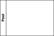 |
Pool symbol - represents a participant in a collaboration, could be a specific entity or role (often used to represent a collection or a group e.g. Accounting, Purchasing, etc.) |
 |
Lane symbol - represents a partition in a process, typically within a pool (often used to represent roles or positions within a collection or group e.g. Accountant, Clerk, Admin, etc.) |
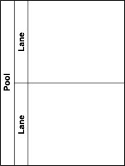 |
Pool with lanes - a demonstration of how lanes can be combined within pools |
There are many variants of the symbols presented above that can help to add more clarity to a process. However, a process can be adequately described using only the symbols presented here.
The following video will show you where to find the relevant BPMN symbols in Diagrams.net.
BPMN Flows #
Symbols are only part of the solution when it comes to creating cross-functional BPMN diagrams. To indicate the order in which tasks and decisions should be made, we need to add flow to the diagram. There are two basic methods for adding flow to a diagram: sequence and message.
Sequence Flow

Sequence flows are required as your diagram wouldn't make much sense without them. A sequence flow is a solid black line with a solid arrow indicating the direction of the flow from one symbol to the next. While it's not necessary, you can label sequence flows to add more context or detail to the process. Sequence flows are used to indicate the flow from one symbol to another within the boundaries of a pool. Sequence flows cannot cross the external boundaries of a pool to connect an external
entity.
Message Flow

When separate entities are included in a diagram (e.g. customer and business unit), sequence flows cannot be used to coordinate the flow between them. To indicate that communication exists beyond the external boundaries of a pool, a message flow must be used. A message flow is a dashed line with an open circle on the originating end and an open arrow indicating the direction of the message. Message flows are almost always labelled to indicate what the message conveys (e.g. receipt, order, confirmation,
etc.).
The following video demonstrates where to find the sequence and message flow symbols in Diagrams.net.
Correct use of Sequence and Message Flows #
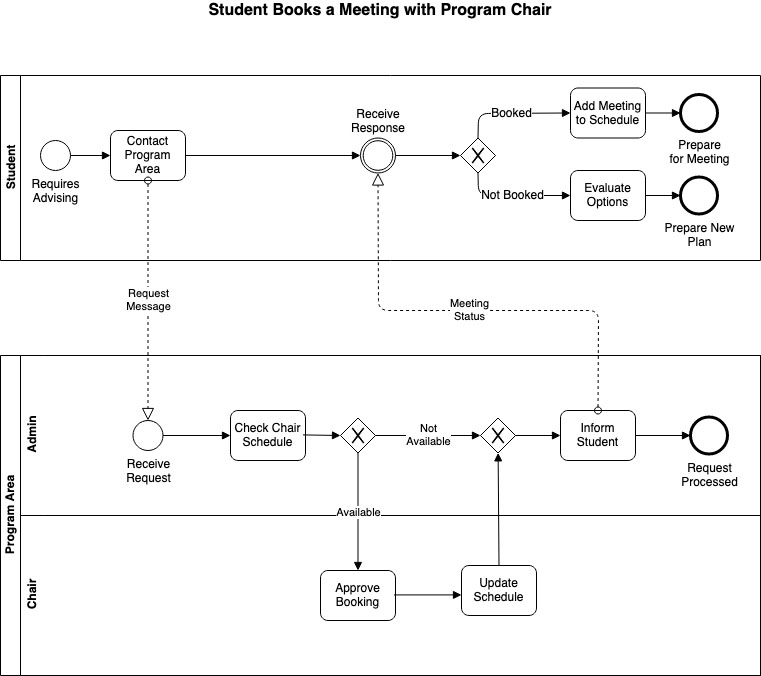
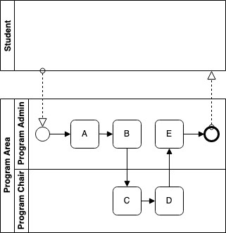
In the following diagram, the generic process (e.g. could be booking an appointment with the Chair) that's being modelled is internal to the Program Area, and therefore does not rely on any specific tasks that the Student performs. As such, the Student is modelled in a separate pool from the Program Area and is not directly involved in the sequence of flows between tasks that take place. Message flows are used to cross the pool boundaries, indicating that it is a message from the student to the Program Area that triggers the process, and that a message of completion is sent back to the Student once the required work is done.
Incorrect use of Sequence and Message Flows #
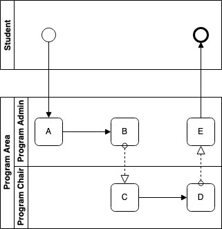
Here, we use the same process as in the previous example, but demonstrate improper use of the flows. While at first glance the diagram appears very similar to the previous version, the flows in this diagram are improperly used. Here, we have begun the process within the Student pool, which on its own isn't anything unusual or unexpected (there are many ways to model the same process). Where things take a wrong turn is with the use of a sequence flow connecting the Student to the Program Area. There are two flows in this diagram that cross the pool boundaries, and they must be represented with message flows, not sequence flows. Likewise, there are two message flows connecting tasks within the same pool, which is not supported by BPMN. Minor differences like the ones demonstrated here might not seem like a big deal, but it is the standardization within diagrams that allows for universal understanding and communication of business processes via BPMN.
The BPMN Quick Guide (https://www.bpmnquickguide.com/view-bpmn-quick-guide/) presents an easy to reference guide to the symbols of BPMN and also lists a number of best practices that you should follow.
Putting it all Together #
The following example diagram illustrates a cross-functional diagram for the simplified process of making an appointment. Pay careful attention to how the symbols, flows, and labels are used in the diagram. One thing to note, while the tasks of the Student are modelled in this diagram, there is no reason why they couldn't be (i.e. we may only decide to show the message flows from the Student pool boundary). When creating your diagrams, it is important to know your audience, and be sure to include as much (or little) information as is necessary based on who needs to know.
You can follow along with the following video to create the diagram shown below.